Definitions
An Line Blender is a mixer in a pipe. This Line Blender is made
of a T-pipe section with 10" diameter. It has a shaft with
2 5"-
radial impellers extending through the T into the pipe.
The impellers are
4 bladed turbines without a disk or RP4. This particular
Line Blender has a baffle plate that forces the fluid to the
upper impeller, through an orifice, and down to the bottom
impeller and back to the pipe. The overall flow is from left
to right. More details.
A detailed study of 4 other styles of In-liners or Pipe Mixers
has just been completed. Which design do you think is the
best? Which one will give you the most mixing for the
least amount of power. The results will amaze you.
| Here is an animation of the vector
plot. Horizontal
slices are taken from the top of the T to the bottom of
the pipe. Each slice is shown for 1 second. To repeat
the animation, right-click and select Play. |
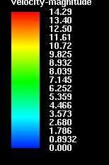
| Velocity [m/s] |
Animation of the
velocity profiles |
Comments |
 |
![A video animation will appear here. Please wait.]() |
|
|
A side view of the Line Blender is shown here as a
CFD mesh. |
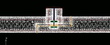
The flow through the pipe is from left to right and
top to bottom.
|
The animation starts at the top of the T.
Horizontal slices move from top - down.
The upper impeller appears first.
Then comes the dividing plate with an orifice.
Then comes the bottom impeller.
It ends at the bottom of the pipe.
|
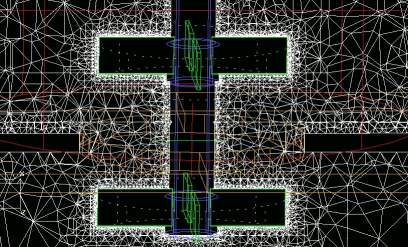
| A close up of the impeller region.
|
|
| If you want to see
these pictures better click on the appropriate
thumbnail below. |
 |
 |
Details of the animation:
Physically, this is a nominal 10" pipe
with "tee", with
flat blade impellers. The fluid is nominally water, and the
flow rate corresponds to 1100 gal/min, and impeller speed of
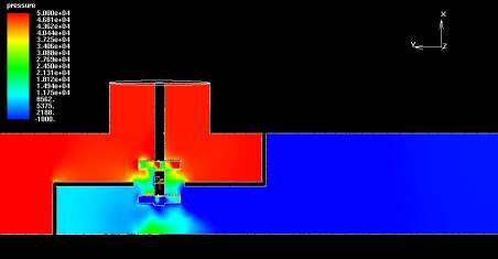
1750 rpm. The pressure drop shown on the vertical pressure plot
below is in Pascals, which corresponds to approx 8 psi in
English units.
The segmented region is 20" long. This means that the volume
in this region is 25.7 Liters = 6.78 gallons.
Just a couple of words about the solution itself - it looks
like there is a "stable" oscillation some where - i.e. I ran about
100 iterations which took just under 7 hours, but the solution
reached its stable oscillating mode in about 20 to 40
iterations depending on how you call it. That is, that the
nonlinear residuals are solved pretty well - and the step to
step velocity was changing. I need to investigate this a bit
further - but usually this is like a vortex moving around -
which is highly probable. The Froude Number is 11!
Discussion of the results:
Assuming that Nq = 0.6, the pumping capacity of each impeller
is 0.0358 m3/s or 567 gallons/min. Compared to the flow through
the pipe (1100 gallons/min), the flow from the impellers are about
1/2 of the flow from the pipe. The animation and the vertical
plot shows an overwhelmed impeller system, which is to be expected
in this case.
In the vertical velocity vector image shown below, you can
see quite well the up stream and down stream flow implications.
The up stream effects are not too large - but this is a function
of the flow parameters - speeds, fluid viscosities, etc. The
down stream shows a significant recirculation loop at the top.
That is not surprising.
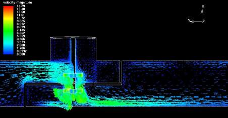
Notice that there are 6 significant regions of less active
zones and recirculation in the Line Blender:
-
The bottom of the upstream pipe before the forward vertical
baffle.
- The top of the T
- The top near the rear vertical baffle
- The bottom near the forward vertical baffle
- The bottom under the rear vertical baffle
- The top of the downstream pipe.
Backmixing and short-circuiting will be a serious
consequence of this arrangement.
The torque and power number when taken about the impeller
axis - is as follows: impeller speed = 1750 RPM, total
torque = 4.865980 Nm, total power = 891.737368 Watts and
total power number = 3.267261. A single, fully baffled 4-bladed
paddle (no disk) would have a power number = 3.4. Obviously, the
power number is less in this unbaffled situation.
The segmented region is 20" long. This means that
the volume in this region is 25.7 Liters = 6.78 gallons. For
this region P/V = 892 Watts / 25.7 Liters = 34.7 kW/m
3 = 173.5 Hp/1000 Gallons.
At 34.7 kW/m3 you would think there was really enough
energy there to mix just about anything! What we see is a
totally swamped impeller. The impellers have no significant
influence on the flow pattern. If the flow was uniform through
the orifice, the velocity would be 4.5 m/s. The tip speed of
the impeller is 11.6 m/s.
|