Mixing Xanthan Gum
Until now, the continuous medium in this report has been water.
The CFD program handles many different types of rheologies. For
Xanthan Gum, a power-law correlation works well. The ACUSOLVE
code represents this as:
mu = mu0 * ( (eta^2) * I2 )^( (n-1)/2 )
mu0 = reference viscosity
eta = a time constant
I2 = second invariant of the strain rate tensor -
which is basically gammadot^2 (from CFD)
n = shear thinning exponent
In this case, the operative constants were mu0 = 2.5 kg/m s,
a shear-thinning exponent of 0.7, and the time constant was set to
1.0. According to our estimates, the apparent viscosity around
the impeller tip region is in the ballpark of 200 cPs, the material
bulk is about 2500 cPs. We used 1000 kg/m3 for the density.
Xanthan Gum is used as an emulsifier, lubricant, suspending
agent, and/or a thickener. We ran our Xanthan Gum, at 1500 RPM and
with a flow rate of 750 GPM in our 10" Schedule 40 pipe.
We used the HGR.
|
 |
 |
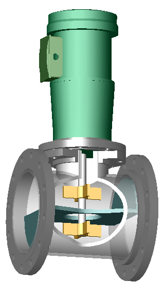
| Figure 25: Tracer study at 650
GPM and 1500 RPM of Xanthan Gum with the HGR. Based on
the colors in the outlet, the distribution of residence time
is wide. The light green area shows an iso-surface where
the Eddy Viscosity is about 50% of the total. The maximum
Eddy Viscosity is 0.010 m2/s, so the green surface
represents 0.005 m2/s. It appears that all of the
tracer particles go through this high shearing region.
Internals other than the impellers and shaft are not shown. |
Both pictures from Figure 25 are under the same conditions.
It is interesting to see that the Eddy Viscosity surface is
not symmetrical. This has to do with the rotational direction of
the impeller and the flow. On the right hand side, the volume is
larger. This is the side where the impeller blades are moving
against the current. On the left hand side, the blades are moving
with the current.
The lower impeller is slightly visible. This means that it is
not completely engulfed in this high-energy zone. Table 1 also
shows that the lower impeller has a lower power number.
The particles are added below the lower impeller. The picture on
the right shows that the tracers are swept toward the back Z-plate
wall before being forced up. Then it appears that every tracer
particle goes into this high-energy zone. It does not appear that
this high viscosity will have a problem mixing in a Process
intensifier.
Figure 26 compares this non-Newtonian case with water. The
residence time distributions look fairly similar. The fastest
and longest times are about the same. Some particles in the Xanthan
Gum only take one second longer to leave the device. The statistics
are given in Table 6. The Eddy Viscosity volume for the water case
is much larger than the Xanthan Gum (Fig 26). Obviously the shear
drops quicker away from the impellers than does water. The power
numbers are essentially the same (see Table 7). The pressure drop
was essentially the same, too. The Xanthan Gum is essentially
behaving like water inside the Process Intensifier.
| HGR |
Np(bottom) |
Np (top) |
Np(total) |
ΔP |
| Xanthan Gum |
2.5 |
3.5 |
5.9 |
3.9 (26690) |
| Water |
2.4 |
3.5 |
5.9 |
3.9 (26890) |
| Table 7: Power numbers for the
HGR impellers and the pressure drop in psi (Pa). |
| HGR 650 GPM 1750
RPM - Water |
HGR 750 GPM 1500 RPM
Xanthan Gum |
 |
 |
 |
 |
|
 |
| Figure 26: Residence Time
Distribution, tracer study, and pressure distribution for
water and non-Newtonian Xanthan Gum in the HGR. Internals
other than the impellers and shaft are not shown. |
Continue with the Conclusions
or Go back to Results
or
Go back to the Title Page
|