Baffles
Importance of baffles
Baffles are needed to stop the swirl in a mixing tank. Almost all impellers rotate
in the clockwise or counter-clockwise direction. Without baffles, the tangential
velocities coming from any impeller(s) causes the entire fluid mass to spin. It may
look good from the surface seeing that vortex all the way down to the impeller, but
this is the worst kind of mixing. There is very little shear and the particles go
around and around like in a Merry-Go-Round. This is more like a centrifuge than a mixer. The presence of baffles stops that. This page is dedicated to the variety of baffles and the effects of their dimensions.
|
|
Baffle schematics courtesy of
P. Csiszar
|
Most common baffle types
Most common baffles are straight flat plates of metal that run along
the straight side of vertically oriented cylindrical tank or vessel. This
baffle design is often referred to as "standard baffles". There are
many nuances. Some may have the baffles extend into the bottom dish or
bottom head. Some may go up the straight side only partially (so-called
partial baffles). Some baffles are flush with the side wall, but the
majority have a space between the baffles and the tank's wall. They are
off-wall.
Number of baffles
Most vessels will have at least 3 baffles. 4 is most common and is
often referred to as the "fully baffled" condition. This basically means
that adding any more baffles doesn't significantly add to the power
consumption of the impellers.
|
 |
Baffle width
Baffle width, wB, is a function of the viscosity. For very high viscous
fluids and broths, baffles are not even required, because there is enough
resistance to flow at the walls. As the viscosity decreases, baffling
becomes important and the baffle width gets larger. Guidelines for baffle width as a function of viscosity
will be here soon.
|
|
In turbulent flows two standards of baffle widths have emerged: Metric
standard(wB=1/10) and the American standard (wB
=1/12). The difference is not large, but it is worth noting. Since the metric
system is built on tenths, it is easy to determine baffle width. If the tank
diameter, T, is 3 meters, then the baffle width is 300 mm. Simple, right? That is
not so simple in those countries using inches and feet for linear dimensions. 1/10th
of 9 feet is 0.9 feet and is not easily converted to inches. Using the 1/12th
rule (0.083), the baffles for a 9 foot tank will be 9 inches in width.
It is important to understand this small difference, 0.083 vs. 0.1,
when looking at power numbers and flow patterns. If the author of the
paper comes from Europe, Asia, or Africa, chances are that the Metric standard
is used (1/10). North American, Central American, South American, and British
may be using the American standard (1/12).
Baffle height
Most baffles start at the bottom tangent line of the lower head and run up to
the top tangent line of the upper head. Some do extend down into the head. If
you have consistent batch volumes or weights, it is best not to extend the
baffles through the liquid surface, unless you want to entrain air into
the batch. Baffles extending through the surface can create vortexes behind
the baffles and entrain air. In viscous media, the baffles can create dead zones
on the surface, and pack-up the material in front of the baffle (in
flow direction). If you are adding sticky solids on the surface, the baffles are
a great place for materials to agglomerate.
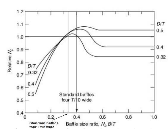
Effect of baffles on the impeller power, the Baffle Factor, or BF
The effect of baffles on the power is often described as the baffle factor, or BF. As you can imagine, 4 baffles will cause the impeller to draw more power than if there were only 3, 2, 1, or no baffles present. The baffle factor is a factor multiplied with the fully baffled, turbulent power number Np, to achieve the apparent power number of the mixer. The Handbook of Industrial Mixing (2004), has a figure (Figure 6-15, page 362) that shows what BF is as a function of baffle configurations. Unfortunately, that figure's X-axis is wrong. Here we show the corrected graph.
The baffle factor in this graphic is labeled Relative Np (Y-axis). The Baffle size ratio, is a dimensionless number consisting of the number of baffles, Nb, the baffle width (here as B), and the tank diameter T. As mentioned above, the metric standard is B=1/10 T and the American standard is B=1/12 T. The lines of 4 standard baffles of each standard are drawn in the graphic. |
 |
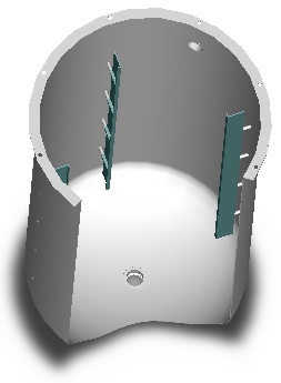
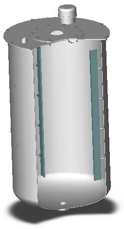
Other types of baffles
Baffles for glass-lined tanks
Straight flat baffles are not found in glass-lined tanks. The types
of baffles for glass-lined tanks often depend on the manufacture. In general,
though, the baffles are supported from the tank top. Baffles usually take on
names that describe what the baffle looks like, such as Beavertail
, F-baffle, and D-baffle. |
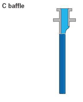
C-baffle courtesy of
Jürgen Reinemuth |
The Pfaudler Werke GmbH
in Schwetzingen,
Germany has kindly notified us that the F- and D-baffles are designs from
the past. They have come out with a brand new patent-pending
baffle design called the C-baffle, that looks to us like it would be
ideal in metal tanks, too. Like all other baffles for glass-lined tanks, it
attaches to the top of the tank through an available port. They can also add
probes to this design. The orientation of the C-baffle to the flow is
interesting and is for baffling what the
Smith Turbine or RS-6 is to
radial flow turbines.
Because of its design, the port can still be used to add liquid and gasses and
be used as a vent if required. This makes it ideal for gas-liquid reactions
in glass-lined tanks that utilize the mass transfer across the fluid surface from
the headspace, like hydrogenations.
|
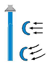
Flow pattern near baffle courtesy of Pfaudler
|
This baffle is shaped like an open C whose opening is directed against
the direction of flow of the fluid moved by the agitator. The geometry
was optimized with respect to minimized bending stress using the Finite
Element Method (FEM). Have you ever seen a flat baffle buckle and bend under
the stress of the mixing action? We have! This shape will keep that from
happening. The cw-value of a C-section is significantly
higher compared to the profile of a classical paddle-type baffle. The cw
-value is a characteristic quantity that describes the flow resistance
of a body. Higher cw-values indicate a higher resistance to flow,
and a better disturbing effect in agitating applications. The
importance of baffling has already been discussed above.
|
|
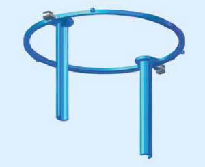
Since glass-lined baffles are attached to the tank top through an
available port, ports can be scarce, especially on the lids of small tanks.
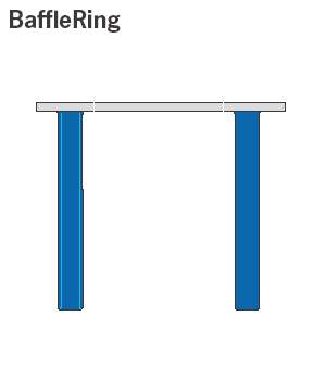
Well Pfaudler came up with another patent-pending idea they call
the BaffleRing. It has a ring-shaped component with two C-baffles attached
to it, which is directly inserted between the lid and the lower reactor body
and fixed by the reactor clamps. Thus, all reactor nozzles are available
as process ports. Furthermore, a so far unknown level of flow disturbance
can be reached inside glass-lined reactors which reduces the mixing times
by up to 60%. Not bad! Finally a great way of reducing the swirl in
glass-lined tanks. Look at the table below how it improves mixing times!
You can read all about these innovations in a
newly released brochure from the
Pfaudler Company. This PDF-file is in English. If you want it in German
please contact Pfaudler directly.
If you reside outside of Europe and Asia and you want to know more about
this interesting development please contact
Pfaudler in the USA.
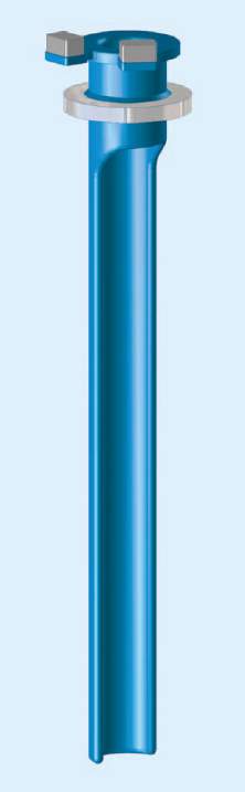
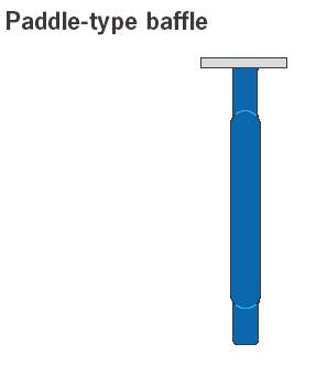
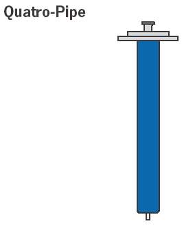
Another baffle-type is called the Quatro-Pipe. This unit is a dip pipe
with the outer shape of the classic Paddle-type baffle. Thus, the
Quatro-Pipe acts like a baffle, but offers the added value of introducing
or removing a fluid into/out of the reactor through an additional nozzle.
But think about this for subsurface aeration, hydrogenation and other
gas-liquid applications, too.
|
| |
|
Paddle-Type |
C-Baffle |
BaffleRing |
Quatro-Pipe |
Current Baffle Types
for Pfaudler Glass-Lined
Tanks |
Nr.
of
baffles |
|
 |
|
|
Relative Baffling effect
4 standard baffles = 1.0 |
1
2 |
0.55
0.75 |
0.79
0.91 |
-
0.91 |
0.55
0.75 |
Relative Mixing Time
Paddle-type baffle = 1.0 |
1
2 |
1.0
- |
0.65
0.40 |
-
0.40 |
1.0
- |
| Gas sparging |
- |
surface |
surface |
surface |
sub-surface |
|
Baffles in the tank bottom
When axial flow down-pumping impellers are used, a crucifix baffle in the
base may be all that is needed. The crucifix baffle is comprised of two plates
that cross (usually in the center). They should not be placed directly on the
bottom of the tank, so that solids don't get stuck.
Baffles in horizontal cylindrical tanks also called autoclaves in the mining industry
Horizontal cylindrical tanks often have baffles at the location of the impeller shaft(s) on the curved walls. They usually come in two basic shapes, the half-moon, and the contour baffles. These types can also be placed on the dished heads of these tanks as well. They are not as affective as standard flat baffles in vertical cylindrical tanks, but are much better than nothing. It is our opinion that the optimum design of baffles for this tank geometry has not yet been made.
Baffles in side-entry tanks
A flat plate baffle in the outlet stream of a side-entry mixer can help
to straighten the flow and reduce the formation of a vortex emitting from
the impeller.
Fluid forces on baffles and baffle plates
To design an agitation system - tank, shaft, impellers, and baffles
(or baffle plate) - each component must be built strong enough to withstand
the fluid forces generated by the impellers. Many calculations and
programs are based on conservative hand-waving ideas based on the torque on
the impeller shaft times some multiplier. This really isn't necessary anymore.
The Acusolve
CFD program that we use, can
accurately determine the fluid forces on baffles, shafts, and the tank walls!
Contact us if you would like a quote to determine
the fluid forces of your mixing system.
|
|
|