Side View
Click here for a larger picture. |
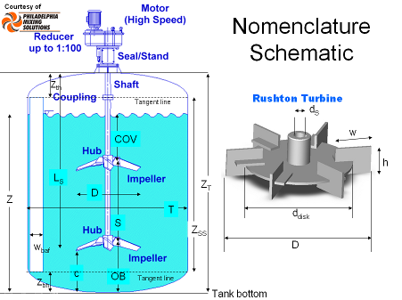
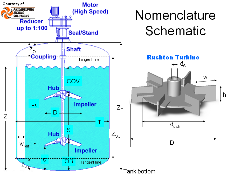
Here is the typical parameters describing a mixing tank with mixer based on the side view of a tank/reactor.
Notice the difference between off-bottom distance, OB, and the impeller clearance, c. The off bottom distance is usually based on the centerline of the impeller hub, or where the impeller is attached to the shaft. The clearance of the impeller is usually based on the lowest impeller point to the bottom of the tank. An important ratio is either the off bottom distance or clearance relative to the impeller diameter, D, i.e. OB/D or c/D. In solids suspension, the relative clearance is often compared to the tank diameter, T, i.e. c/T.
Not shown in this diagram is the off-wall spacing of the baffles. There is usually a gap to allow for flow to go behind the baffle and keep it clean.
For the full list of variables, see the Nomenclature page.
Most impellers are proprietary and the only parameter of importance is the impeller diameter, D. For those that are generic, like the Rushton Turbine shown here, the nomenclature is shown to the right. Be careful with blade geometry, because often the blade height, h, is called the blade width, and the blace width, w, is often called the blade length. |
Side-view of a typical tank
This tank is equipped with two heat transfer devices. Both of them are
filled with a fluid, which is circulated (pumperd) through a heater or
chiller to bring the fluid into the tank to a desired temperature.
The copper looking structure is the helical
coil. The spacing of the pipe has been exaggerated to show the insides
of the tank. Usually this spacing is about 1 to 2 pipe diameters.
The heat transfer jacket is like an outer tank surrounding the
inner tank. The heat transfer fluid flows between the two tanks.
This tank is equipped with 4 straight
standard baffles, 3 of which
are visible in this cut-out view. They are attached to the tank wall and
the baffles are spaced away from the wall.
The central silver colored rod is the shaft. This can be solid or
hollow (pipe shaft). When the design calls for a large diameter shaft, pipes
are often used to reduce cost, weight and to add strength. Shafts don't float
in a tank. The upper flange is attached to the outboard shaft of the
gearbox, which is not shown. |
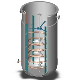
Courtesy of P. Csiszar
|
|
The blue structure is called an intermediary steady bearing. It surrounds
the shaft with bearings. Sometimes this could be just a ring which is called
a limit ring. Both of these devices protect the internals of a tank in the
case that the fluid forces would otherwise bend the shaft. Many tanks have
a steady bearing or a limit ring near the bottom of the tank. Instead of
being suspended from the walls, they rest on top of a tripod, which is
attached to the bottom of the tank.
This tank is equipped with 3 silver colored impellers. This particular example shows
them to be low solidity hydrofoils (our example is of the LIGHTNIN
A310)
We also see a drain hole in the bottom of this tank. |
