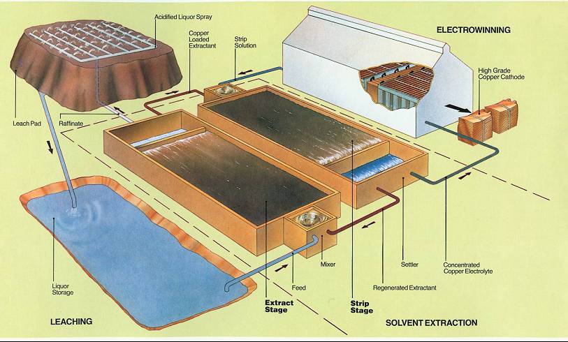
Background - Solvent Extraction Systems
This is a simplified schematic of an SX plant using Mixer-Settlers. Here is a simplified explanation of the solvent extraction process for base minerals. This process can be used for copper, nickel, molybdenum, uranium, and many other rare earths. The number of stages depends on the isotherms and the mineral/solvent equilibriums. Notice that there are 3 flow loops in a typical SX plant: 2 aqueous and one organic. While the organic (red loop) cycles between the Extract and Strip Stages, the aqueous PLS/raffinate (blue loop) cycles between the leaching area (heap and PLS pond) and Extract Stage, and the aqueous heavy/barren electrolyte (green loop) cycles between the Strip Stage and the Electrowinning house.
Leaching phase: A leach pad or heap is sprinkled with an aqueous acidic solution. In this schematic it is described as the acidified liquor spray. This comes from the raffinate of the extraction stage(s). The liquid passes through the heap, dissolving minerals along the way. It is typically collected in a pond, which is affectionately called the pregnant leach solution or PLS.
Extraction phase: Through gravity or from the suction of the pumper mixer in the Extract Stage, PLS is mixed in a pump-box (mixer, pumper stage) with an organic solution often referred to as the barren organic (here called Regenerated Extractant coming from the Strip Stage) to form a liquid-liquid dispersion. Mass transfer occurs and ideally only the desired mineral transfers selectively from the aqueous phase to the organic phase. In this schematic, the mineral is copper. In most SX plants, there is usually a pump-box followed by one or more auxiliary mixing tanks. Their purpose is to maintain the dispersion and give more residence time for the extraction to take place. Then the dispersion is sent to a settler, where the two phases disengage. The lighter fluid (organic) is removed from the top, while the heavier fluid (aqueous phase) is removed from the bottom of the end of the settler. The aqueous is now called raffinate and is returned to the heap or leach pad. It contains lots of dissolved minerals, but very little of the desired mineral. The aqueous cycle is complete. The organic (labeled above as Copper Loaded Extractant), now heavy with the desired mineral, is pumped into the Strip Stage.
Stripping phase: The loaded organic extractant is mixed with the aqueous lean electrolyte (hear strip solution) to form another liquid-liquid dispersion. Due to a shift in pH, the desired mineral transfers back from the organic phase to the aqueous phase. Once again, it is not unusual to find one pump-box followed by one or more auxiliary mixing tanks to achieve the desired residence time and mass transfer efficiency. The dispersion is again sent to a settler so that the two liquid phases can be separated again. A portion of the aqueous phase, called here the Concentrated Copper Electrolyte, is pumped to the Electrowinning house, while the rest is recycled back to the Strip Stage (not shown above). Pure copper (desired purity is called five-nines = 99.999%) is deposited on plates, pulling the copper out of solution. This solution is called the lean electrolyte, or here as the strip solution, and returns to the Stripper. This completes this aqueous loop. The barren organic (here called regenerated extractant) returns to the Extractor to complete the organic loop.
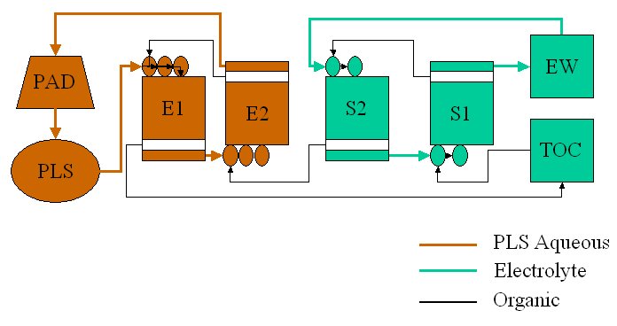
Traditional SX Circuit Design for Copper: 2 Extract - 2 Strip
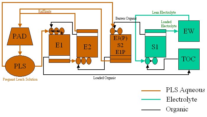
Modified SX Circuit Design for
Copper: 2 Extract - 1 Parallel Extract - 1 Strip
This method almost doubles the throughput of copper, because E1P (or E3(P)) replaces the former S2 allowing essentially twice the copper to be processed. Although the single stage E1P will not have the same transfer efficiency as the dual stage E1-E2, the copper remaining in the raffinate goes back to the pad and will eventually come back to the plant to be processed another day.
Regardless of the SX circuit layout, each stage is treated in the same way with CFD. The only difference is the density (and other properties) and flow rates through each stage. E1 and S1 are often not only pumped by the pumper-mixer, but are also externally fed by gravity or through additional pumps from the PLS or TOC (total organic container = inventory storage).
A
side-view schematic with general flow pattern of a Mixer-Settler has been described in another article.
SX Pumper Characterization
|