|
|
|
|
CFD Solid Shapes
|
This is a continuation of the
Process Intensifier - Optimization with CFD: Part 1 paper.
Animations
| CFD model shapes
|
Radial Process
Intensifier |
Axial Process Intensifier |
| Lightnin |
 |
 |
| |
Model LTR |
Model LTA |
| Hayward Gordon |
 |
 |
| |
Model HGR |
Model HGA |
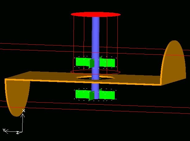
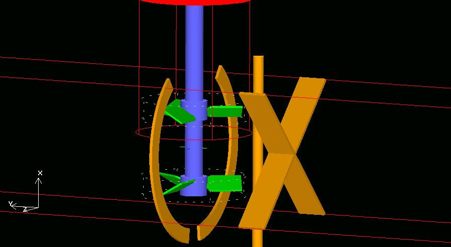
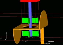
| Figure 5: CFD model shapes of the 4 Process Intensifiers studied in this project. All were enclosed in a 10" (254 mm) Schedule 40 pipe. Flow rates studied were 0, 650 (148 m3/hr), and 1100 GPM (250 m3/hr) and come from the right. Impeller speed was 1750 RPM. The tan objects are stationary surfaces. The red object is the top of the T-pipe section. The shaft is blue and the impellers are green. The rotating reference frame tightly surrounds each impeller individually.
|
Continue with Experimental Design subtopics...
Dual Radial Process Intensifiers |
Axial Impeller Process Intensifiers
|
Standard Geometries
or skip the Experimental Section
Continue with Results or
Go back to the Title Page
|
|
|