This is a continuation of the
Process Intensifier - Optimization with CFD: Part 1 paper.
Process Intensifiers with Dual Axial Impellers
| LTA
|
HGA
|
 |
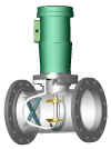 |
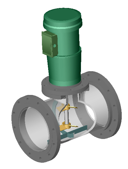
| Figure 3:
Lightnin Line Blender with dual axial
PBT
impellers and a crucifix baffle. Click on the picture
for a bigger picture |
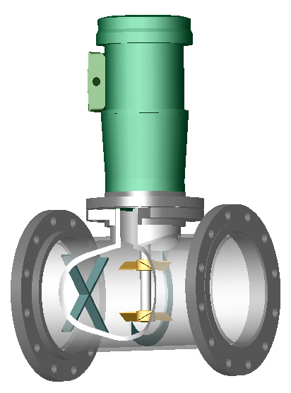
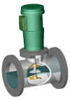
Figure 4: Hayward Gordon
In-Line Mixer with dual axial PBT
impellers, a segmented ring baffle, and a
criss-cross flow straightener. Click on the picture for a
bigger picture |
Figures 3 and 4 show schematically the general concept of a Process
Intensifier with axial flow impellers. The differences between the two models
are:
- Impeller locations
- Impeller diameters
- Flow orientation of the impellers
- Baffle style and positions
- Presence of flow straighteners
- Inlet position of secondary fluids to be mixed in
The general flow pattern is from the left to right in these illustrations. A
Z-divider plate with orifice does not exist in these tested models. That is not
to say that the vendors would not offer this as an option (see Figures 3a and
4a).
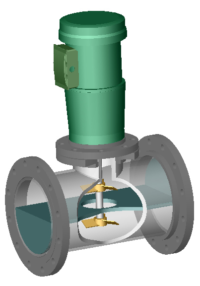
| LTA-with
Z-plate |
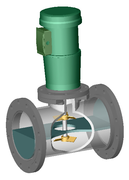
HGA-with
Z-plate |
 |
 |
| Figure 3a: Lightnin Line
Blender with dual axial
PBT
impellers and a Z-plate (not studied). Click on
the picture for a bigger picture |
Figure 4a: Hayward Gordon
In-Line Mixer with dual axial
PBT
impellers and a Z-plate (not studied). Click on
the picture for a bigger picture |
Model LTA: The Lightnin Line Blender model (Figs. 3,5) has dual 3.5"
(88.9 mm) axial 3-bladed PBT impellers with a blade width to impeller diameter ratio
of w/D = 0.25. D/T is approximately 1/3. Although Lightnin would use hydrofoils,
our model approximates the hydrofoil by using 3 blades at 30 degrees. Both
impellers are down-pumpers. The distance of the centerline of each impeller to
the top and bottom of the pipe is 2.5" (63.5 mm) and the spacing between
the impellers is S = 5" (127 mm). There are two baffles. One baffle is
shaped like a horseshoe and is on the wall of the pipe at the centerline of the
shaft. It is continuous around the pipe except at the top, where it is open
enough to allow insertion of the impellers. Another baffle runs the length of
the pipe section to form a cross directly under the lower impeller. This is the
pipe version of a standard crucifix baffle configuration. A secondary fluid to
be mixed would enter the pipe 5 to 10 impeller diameters in front of the Line
Blender through a T, depending on the flow rate.
Model HGA: The Hayward Gordon In-Line Mixer model (Figs. 4,5) has dual
5" (127 mm) axial 3-bladed PBT
impellers with w/D = 0.25. D/T is approximately
1/2. Although Hayward Gordon would use hydrofoils, our model approximates the
hydrofoil by using a pitched bladed turbine with 3 blades at 30 degrees. The
distance of the centerline of each impeller to the top and bottom of the pipe is
3" (76 mm) and the spacing between the impellers is S = 4" (102 mm).
The top impeller is a down-pumper, while the bottom impeller is an up-pumper.
One baffle is a horseshoe baffle on the wall of the pipe at the centerline of
the shaft. It is interrupted on the bottom by a 10-degree gap and at the top,
where it is open enough to allow insertion of the impellers. A criss-cross flow
straightener also precedes the impellers. A secondary fluid to be mixed would
enter through a vertical pipe half way between the flow straighteners and the
impeller blade tips.
Continue with Experimental Design
subtopics...
Dual Radial Process Intensifiers |
CFD Solid Shape Models
|
Standard Geometries
or skip the Experimental Section
Continue with Results or
Go back to the Title Page
|