This is a continuation of the
Process Intensifier - Optimization with CFD: Part 1 paper.
Description of the equipment tested
An Internet search yielded four different commercially available Process Intensifiers. There may be some slight differences between the designs studied here and what is actually commercially available. We did not consult the vendors directly, but based the designs on information available at their respective Internet sites or brochures (see References).
We limited our comparison to studying Process Intensifiers in horizontal
Schedule 40 10-inch (254 mm) pipes (T = 10 inches) with a flow of Q = 1100 GPM
(250 m3/hr) and running at motor speed (N = 1750 RPM). This flow rate is right
in the middle of the applicable flow range for Schedule 40 10" pipes (v =
1.37 m/s)(Fisher Control Valve Handbook 1977). Some tests were done at Q = 650
GPM (148 m3/hr), which represents the average flow rate when using 8-inch (43
mm) pipe (v = 1.26 m/s). Process Intensifiers with 10-inch pipes could easily be
flanged to 8-inch pipe in order to decrease the linear velocity inside the
Process Intensifier (v = 0.81 m/s for 650 GPM).
| Design |
LTR |
HGR |
LTA |
HGA |
Case R |
Case A |
| Impellers |
Dual Radial
RP44-bladed paddles |
Dual Radial
RP44-bladed paddles
|
Dual Axial
3-bladed
PBT 30 deg |
Dual Axial
3-bladed
PBT 30 deg |
Single Radial
RP44-bladed paddles |
Single Axial 3-bladed
PBT30 deg
|
| D |
5 (127 mm) |
5 (127 mm) |
3.5 (88.9 mm) |
5 (127 mm) |
5 (127 mm) |
5 (127 mm) |
| h/D or w/D |
0.20 |
0.30 |
0.25 |
0.25 |
0.20 |
0.25 |
| OB |
3 (76 mm) |
3 (76 mm) |
2.5 (63.5 mm) |
3 (76 mm) |
4.2 (107 mm) |
4.2 (107 mm) |
| S |
4 (102 mm) |
4 (102 mm) |
5 (127 mm) |
4 (102 mm) |
- |
- |
| Picture |
 |
 |
 |
 |
 |
 |
| Other Features |
Long Z-plate
L = 19.7
(500 mm),
DO = 5 1/8
(130 mm) |
Short Z-plate
L = 7.9
(200 mm),
DO = 5 1/8
(130 mm)
and flow straightener. |
Both impellers are down pumping. Crucifix baffle (Horseshoe and straight baffle crossing on bottom of pipe. |
Upper impeller is down pumping, lower impeller is up pumping. Segmented horseshoe baffle, and a criss-cross flow straightener. |
T = 12.5
(317.5 mm)
4 full height standard baffles
wB/T=0.1
Z/T=1 |
T = 12.5
(317.5 mm)
4 full height standard baffles
wB/T=0.1
Z/T=1 |
| Fluids |
Water |
Water |
Water |
Water
Xanthan Gum |
Water |
Water |
| CFD Model |
 |
 |
 |
 |
 |
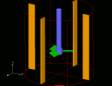 |
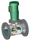
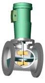
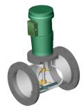
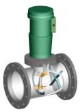
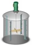
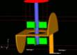
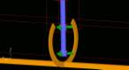
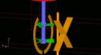
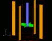
| Table 0: Overview description of equipment tested. Dimensions are in inches (mm). D: impeller diameter, h: blade height, w: blade width, OB: off-bottom distance, S: impeller spacing, L: length of Z-plate, DO: Orifice diameter, Z: liquid level, T: tank or pipe diameter. The general flow pattern in all figures is from right to left. CFD Model: The tan objects are stationary surfaces. The red object is the top of the T-pipe section. The shaft is blue and the impellers are green. The rotating reference frame tightly surrounds each impeller individually. The pipe and T are not shown. |
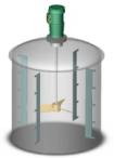
Lightnin denotes their Process Intensifiers as Line Blenders, whereas Hayward Gordon calls them In-Line Mixers. Each vendor has dual radial and dual axial impeller designed units. They differ basically that the radial impeller design includes a divider in a "Z" shape with a central orifice that directs the flow from a generally horizontal flow pattern to a vertical flow pattern, passing by each radial flow impeller. The axial impeller designs do not have this Z-plate in this study. In all studies water and inert tracers were used. An application with high viscosity non-Newtonian Xanthan Gum demonstrates the usefulness of using Process Intensifiers for such processes.
Continue with Experimental Design subtopics...
Dual Radial Process Intensifiers |
Axial Impeller Process Intensifiers
|
CFD Solid Shape Models
|
Standard Geometries
or skip the Experimental Section and...
Continue with Results or
Go back to the Title Page
|