This is a continuation of the
Process Intensifier - Optimization with CFD: Part 1 paper.
Process Intensifiers with Dual Radial Impellers
| LTR
|
HGR
|
 |
 |
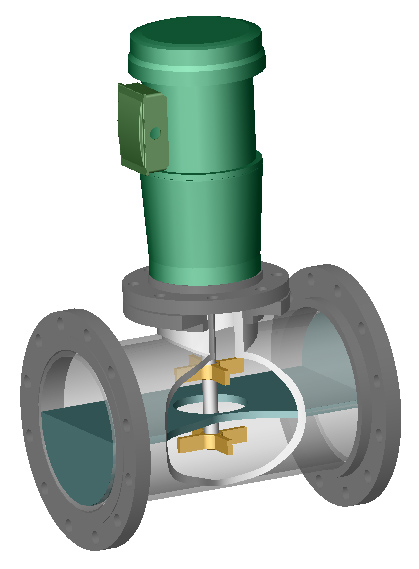
Figure 1: Lightnin Line Blender with
dual radial RP4
impellers and a long Z-plate.
Click on the picture for a
bigger picture |
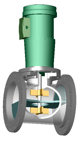
Figure 2: Hayward Gordon In-Line Mixer
with dual radial RP4
impellers and a shortened Z-plate and flow straightener.
Click
on the picture for a bigger picture |
Figures 1 and 2 show schematically the general concept of a Process
Intensifier with radial flow impellers. The differences between the two models
are:
- Blade heights
- Distance between the Z-plate pipe separation ends
- Presence of a flow straightener
Flow always enters the lower chamber, going through the orifice and out the
upper chamber. The general flow pattern in the figures is from right to left. A
secondary fluid to be mixed would enter the lower chamber directly under the
lower impeller. Each chamber has one radial impeller.
Model LTR: The Lightnin Line Blender model (Figs. 1,5) has dual 5" (127
mm) RP4 radial 4-bladed paddles with a blade height to impeller diameter ratio of
h/D = 0.20.
The distance of the centerline of each impeller to the top and
bottom of the pipe is 3" (76 mm) and the spacing between the impellers is S
= 4" (102 mm). The distance between the Z-ends is 19.7" (500 mm), or
approximately L/T = 2.0. The orifice diameter is 5 1/8" (130 mm). That
makes the linear velocity through the orifice 1026 FPM (5.21 m/s) at 1100 GPM
and 606 FPM (3.08 m/s) at 650 GPM. The orifice plate is in the horizontal center
of the pipe.
Model HGR: The Hayward Gordon In-Line Mixer model (Figs. 2,5) has dual
5" (127 mm) RP4 radial 4-bladed paddles with h/D = 0.3. The distance of the
centerline of each impeller to the top and bottom of the pipe is 3" (76 mm)
and the spacing between the impellers is S = 4" (102 mm). The distance
between the Z-ends is 7.9" (200 mm), or approximately L/T=0.75. The orifice
diameter is also 5 1/8" (130 mm). That makes the linear velocity through
the orifice 1026 FPM (5.21 m/s) at 1100 GPM and 606 FPM (3.08 m/s) at 650 GPM.
There is also a vertical flow straightener (not shown in Fig. 2) prior to
entering the lower flow chamber (see Fig. 5).
Continue with Experimental Design
subtopics...
Axial Impeller Process Intensifiers |
CFD Solid Shape Models
|
Standard Geometries
or skip the Experimental Section
Continue with Results or
Go back to the Title Page
|